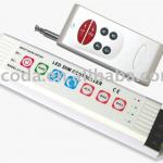
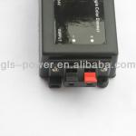
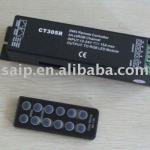
dmx touch controller,dmx decoder with touch remote - AFL-DMX101
| Place of Origin: Guangdong China (Mainland) | Brand Name: anfunet | Model Number: AFL-DMX101 | Type: Remote Control |
| Max. Load Power: 5V<75W,12V<180W,24V<360W | Voltage: 5V,12V,24V |
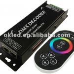
dmx touch controller,dmx decoder with touch remote
Summarization
The DMX decoderadopts the advanced micro control unit,itreceives standard DMX-512 digital control signal that is widely used in the and transformes it into PWM signal to drive LED; the port of DMX signal has lightning protection measures, while the load output has over-current protection circuit; You could connect the DMX decoder with DMX digital console to achieve dimming or various changes in procedures. Not connectied with DMX console, you can choose select the built-in 11 kinds of default patterns through the wireless remote control.
Technical Parameters
Controller
1.Working temperature:-20-60°C
2. Input voltage:DC5-24V
3.Output:3 channels
4. Connection mode: common anode
5.External dimension:L175 x W53 x H27(mm)
6.Packing size:L180 x W58 x H58(mm)
7.Net weight:300g
8. Gross weight:350g
9.Output current: <5A (each channel)
10Output power: 5V:<75W, 12V:<180W, 24V:<360W
Touch remote
1.Working temperature: -20-60°C
2. Power supply mode: AAA*3 battery
3.Supply voltage: 1.5V*3
4.Standby power consumption:0.015mW
5.Standby current: 3uA
6.Emission current: 10mA
7.Remote distance: 15m
8.Standby time: 6 months
Interface Specification
Interface of DMX signal adopts RJ45 cable interface, wiring is as follows:
DMX IN: input interface of DMX signal, D+ should be connected with positive of signal, D- connected with negative of signal, Gnd connected with ground.
DMX OUT: output interface of DMX signal, D+ should be connected with positive of signal, D- connected with negative of signal, Gnd connected with ground.
Power and load output adopts the 6PIN green terminal, wiring is as follows:
POWER: input interface of power, V+ should be connected with positive of power, V- connected with
negative of power, the range of supply voltage is DC5-24V
OUT PUT: load output interface, V+ should be connected with the positive of light, R, G, B connected with
negative, correspond to the three channels.
Mode changes table is as follows:
| Mode number | Function | Remark |
| 1 | Static red | brightness is adjustable,Speed is unadjustable |
| 2 | Static green | |
| 3 | Static blue | |
| 4 | Static yellow | |
| 5 | Static purple | |
| 6 | Static cyan | |
| 7 | Static white | |
| 8 | Three color jumpy changing | Speed is adjustable, brightness is unadjustable |
| 9 | Three color gradual changing | |
| 10 | Seven color jumpy changing | |
| 11 | Seven color gradual changing |
Typical Application
| Packaging Detail:Export standard packing |
| Delivery Detail:3-5days |


