
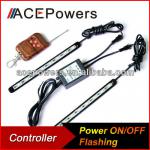
Digital SD Card Led Controller,SD Card Led Strip Controller - BG2010-X
| Place of Origin: Guangdong China (Mainland) | Brand Name: Bright | Model Number: BG2010-X | Type: Remote Control |
| Voltage: DC12V-DC24V,DC5V, 12V , 24V for option | Warranty: 2 years | Certificate: CE,RoHS | output: 2 channels |
| output current: <60 mA | working temperature: -20-60 °C | One way can control: 512 points | Color: Silver |
| Origin: China |
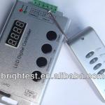

RF Remote Digital LED Controller
The Digital LED strip can be used with the special designed which developed by our company, it can realize different kinds of color changing mode such as 7 color static changing, waterflowing, chasing, gradual changing, flashing, proliferation with the inner fixing light programs controller, total is 133 kinds of program.
TECHNICAL PARAMETER OF CONTROLLER
| Working temperature | -20-60°C |
| Supply voltage | DC12V |
| Current | <60mA |
| External dimension | L137*W70*H25 mm |
| Packing size | L137*W80*H54mm |
| Net weight | 180g |
| Gross weight | 270g |
| Effects model | 133 |
| Maximum control points | 1024 (Low-speed) points, 2048 (High-speed) points |
| Controlled IC Model | Such as the TM1803, TM1804, TM1809, , TM1812, UCS1903 etc. (specify the required model on orders) |
STEERING MANUAL
1). Connect the load well wire at first, following by the power wire; Please ensure short circuit can not occur between connecting wire before you turn on the power. Then set the steps as follows.
2). Press the "On / off" button to take the controller off before setting the menu.
3). Press the “up”, “down” button one time at the time, and LED would be bright at this moment. Then press the "Mode / Speed" button to get into the menu settings screen.
4). The first setting screen is for “High-speed, low-speed settings”, and the LED would display "S-HI" or "S-LO". Then press the “up” and “down” button to select the mode. (If the IC on the light bar is high-speed mode, you should choose “S-HI”, and choose “S-HI” when low-speed.) The factory default is for the high-speed mode.
Continue to press the "Mode / Speed" button to enter the second screen-“Control points setting”. The LED display 4-digit is for the number of control points. To plus or minus the number by pressing the “up” and “down” button (Long pressing can adjust quickly). The factory default is for 50.
5). As set well, press the "On / off" button to save and exit.
6). There are 4 buttons in total on the control panel, function of each button as below:
On/off: It can open or close output.
Mode/Speed: Mode adjustment / speed adjustment function switch (The first LED displays H for model adjustment, shows S for the speed adjustment.)
UP: Mode+/Speed+ button. When in mode regulator function, it is for “Mode+”. When in speed regulator function, it is for “Speed+”.
DOWN: Mode-/Speed- button. When in mode regulator function, it is for “Mode-”. When in speed regulator function, it is for “Speed-”.
7). Adopt wireless control method, 4keys in total, function of each key as below:
A: Mode adjustment / speed adjustment function switch (The first LED displays H for model adjustment, shows S for the speed adjustment.)
B: Mode+/Speed+ button. When in mode regulator function, it is for “Mode+”. When in speed regulator function, it is for “Speed+”.
C: Mode-/Speed- button. When in mode regulator function, it is for “Mode-”. When in speed regulator function, it is for “Speed-”.
D: On/Off button: It can open or close output.
Note: After powering, the red light would bright. And each press, the green light flash one time.
8). Synchronous controller system description
Synchronous control system can be made of any number of controller connections. Each of the sub-controller would follow to the first master controller to achieve a permanent synchronous change. And there is not delay.
After connecting the wiring diagram, the sub-controller need not be set. It will be in accordance with the master to controlling the speed and mode change. (That would be not synchronous when powering. You could close and open to be synchronous) When master is working, and the sub-control working well, the green signal light of sub-control would flick. The digital LED display the mode in operation.
APPLICATION CONNECTION 1
APPLICATION CONNECTION 2
(Each controller can be individually powered, can also share power) Application of synchronization:
(Cascade Connection)
(Bus connection)
1. Supply voltage of this product is DC12VV, never connect to others or AC220V.
2. Wireless Remote Control is powered by DC12V battery, if Stretch the antenna, it would Control better.
3. Lead wire should be connected correctly according to grade that connecting diagram offers.
4. If the load is more, by way of port 2 to connect the power will be better.
5. This product is not to overload;
6. Warranty of this product is three years, but exclude the artificial situation of damaged or overload working.
Express Delivery:
Payment Terms:
1.T/T (in advance)
2.Paypal
3.Western Union
| Packaging Detail:1pc/carton |
| Delivery Detail:5-7 working days |
Related Product for Digital SD Card Led Controller,SD Card Led Strip Controller
24 Key IR Remote Controller For LED RGB 5050 3528 Light Strip
24 Key IR Remote Controller1.CE&RoHS Certificate
2.1years warranty
3.DC 12V 6A
4.IR Remote Control
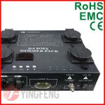
D4 4CH*1KW Digital dimming system for Par 64 light
Digital dimming system for Par 64 light1.4CH*1KW
2.Dimmer curve:linear and switch
3.Warranty:3 years
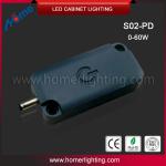
Blue indicator light 12v touch switch, touch and dimma 12v touch switch
1.S02-pd 12v touch switch approved CE,ROHS2.Rated Power: 0-60W
3.Voltage: 9.5-30VDC
4.Output current:0-30A
Flashing led light original remote control/on-off 12V programmable led light controller/LED DRL Wireless Remote controller
Original remote control1.Voltage 12V
2. Strobe mode,steady light,flash synch
3.Save power long lifespan
4.Excellent service
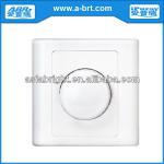
220V LED Dimmer Switch Push on/off Rotary Brightness Triac
220V LED Dimmer Switch1. good for all 220V LED lights
2. easy installation
3. wide dimming range
4. no flickering
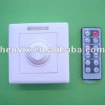
Single Color LED Strip Dimmer Switch Remote LED
Single color dimmer switch remote1,12 key infared dimmer
2,Easy installation
3,Wireless remote controller/Manual
4,CE,RoHS

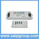
wall mounted rgb led touch controller six RF remote control to one receiver with 4,096 per channel grayscale
1.with 4,096 per channel grayscale2.Output:3A x 3CH (12V/24V)
3.LED mini controller six RF remote control to one receiver
LED constant voltage dimmer with button & RF CT110A
1.PWM dimmer2.remote controller
3.0-100% brightness control
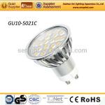
4.0W GU10 LED Lamp (GU10-5021C)
4.0W GU10 led Lamp (GU10-5021C)1. Energy saving
2. Long lifespan:>50000h
3. CE & RoHS
4.Factory directly supply
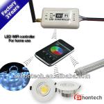
2013 new led dimmer 288w dc 12v 24v rgb led controller wifi
1) Wifi light switch2) Support Android system RGB LED WiFi Controller
3) DC 5~24V, 3 channels, 4A/CH output
4) CE&RoSH

Video outdoor phone/video outdoor station
door phone system1,Use the black high-strength tempered glass panel
2,crystal clear
3,7 inch LCD display
4,LED Floodlight
wholesale 2w led wall dimmer 2LEDs two diretion
1,2w led wall dimmer2,Safety Assurance:RoHS and CE
3,Luminous Opening :Point
4,The price advantage,quality assurance